Case study · CFD · BARC · 2018
Shell-and-tube heat exchanger optimisation
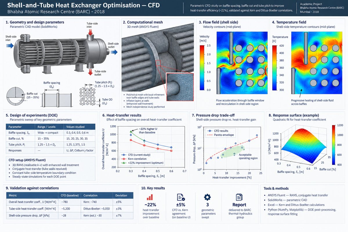
Parametric DOE on baffle spacing and tube pitch to improve heat-transfer efficiency by ~22%, validated against Kern and Dittus-Boelter correlations.
Problem
Shell-and-tube heat exchangers are the workhorses of process-heat plants, but their performance is strongly conditioned on geometry choices — baffle spacing, baffle cut, and tube pitch — that are often set by rules of thumb. The BARC team wanted a defensible numerical basis for those choices on a specific exchanger configuration: how much could heat-transfer effectiveness be improved within a realistic parameter window, and what was the corresponding pressure-drop penalty? The question mattered because the process-side pumping cost was non-trivial, so any efficiency gain had to clear a pressure-drop threshold to be worth doing.
Approach
- Parametric CAD model — SolidWorks geometry parameterised on baffle spacing, baffle cut percentage, and tube pitch, so each DOE point was a clean variant of the same base model.
- 3D CFD in ANSYS Fluent — turbulent flow on the shell side (realisable k-ε with enhanced wall treatment), conjugate coupling through tube walls, constant-temperature boundary on the tube-side fluid to isolate shell-side performance.
- Design of experiments — a structured sweep across baffle spacing (wide to compact), baffle cut (15–35%), and tube pitch (triangular, 1.25–1.5 × tube OD). Each point returned overall heat-transfer coefficient U, pressure drop ΔP, and the Colburn j-factor.
- Surrogate response model — quadratic response surfaces fit to U and ΔP over the DOE. This made the performance–pressure-drop Pareto visible without running new CFD for every what-if.
- Analytical validation — Kern method for shell-side film coefficient (the incumbent correlation BARC used for hand calculations) and Dittus-Boelter for tube-side — a sanity check that the CFD was in the right ballpark before interpreting the DOE trends.
Tools & setup
- ANSYS Fluent — shell-side 3D RANS with realisable k-ε and enhanced wall functions; tube walls resolved for conjugate heat transfer.
- SolidWorks — parametric CAD of the baffled shell-and-tube bundle.
- Excel — Kern-method and Dittus-Boelter hand-calculation sheets for analytical cross-checks.
- Python (NumPy, Matplotlib) — DOE post-processing, response-surface fits, Pareto visualisation.
Results
The gain was not free — tighter baffle spacing drove ΔP up with roughly the square of the shell-side velocity. The useful output was the Pareto envelope: a set of configurations that bought heat-transfer gain at an acceptable pressure-drop cost, not a single "best" geometry.
Validation
Kern-method hand calculations on the baseline geometry agreed with CFD-predicted U to within roughly ±5%, which was the expected error given Kern's empirical origins. Tube-side Nu from Dittus-Boelter matched CFD tube-side heat-transfer coefficients to within ~3% across the Reynolds range. Where Kern and CFD diverged at the tightest baffle spacings — CFD predicted a larger effective shell-side coefficient than Kern — the divergence was traced to flow acceleration through the baffle window, which Kern's correlation does not capture cleanly. That divergence was noted as a known limitation of the analytical method rather than a CFD error.
Lessons learned
- For shell-and-tube geometry choices, a response-surface fit over a modest DOE is worth far more than a finer single simulation. The Pareto shape was the deliverable, not any one operating point.
- Kern is still useful as an upfront sanity check — if the CFD and the correlation disagree by 2×, the CFD is probably wrong.
- Pressure drop dominated the gain conversation. Heat-transfer improvements that required doubling pumping power would not have been accepted; framing the result as Pareto, not optimum, changed how the BARC reviewers engaged with it.
Artifacts
- BARC project trainee report (2018) — CFD methodology, DOE results, Kern comparisons.
- Python DOE post-processing scripts (available on request).